Interested in learning more about this topic and more social and sustainable ways of doing architecture? Apply now for our Postgraduate!

DISCLAIMER
[This article shows the development of the first step of a new prototype experimented in Critical Concrete. During the conception of the green roof, the structure was checked by a civil engineer who also advised us in the development of our wildest prototypes.]
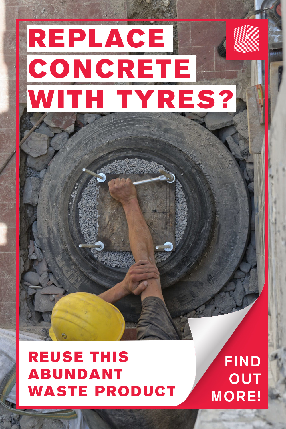
Check out the video to see how we experimented with scrap tyres and compressed earth&gravel for a low-impact and concrete free building!

Introduction
In the progress of developing our green roof prototype we have been confronted with foundations in different ways. Seeking for alternatives it turned out that the old granite walls of the building, once reinforced by wooden beams, would be strong enough to carry the load of the new roof. You can read all about the refurbishment and reinforcing of the walls for the roof in our previous articles (walls-refurbishment 1.0, walls-refurbishment 1.1, how to build a stone wall).
The size of the new roof however, stretches out further than the fully loadable walls. For that reason, part of the roof needs a different kind of foundation.
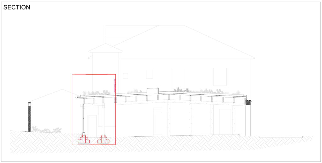
Section of the green roof highlighting the parts supported by tyre foundations
Our Research
Throughout our research for alternatives to concrete, we stumbled over the tyre foundation. For us, it was very interesting since it is a low-tech solution which is composed only of scrap tyres filled with compressed gravel. Both components are easily accessible almost everywhere in the world.
Indeed, when tyres worn out, they become a waste which is not easy to handle. Recently, more processes that aim at recycling have been developed from which rubber, steel and textile fibers are obtained. Another solution is to reuse the tyres directly in a different context, thus avoiding more energy consumption for the transformation of the product.
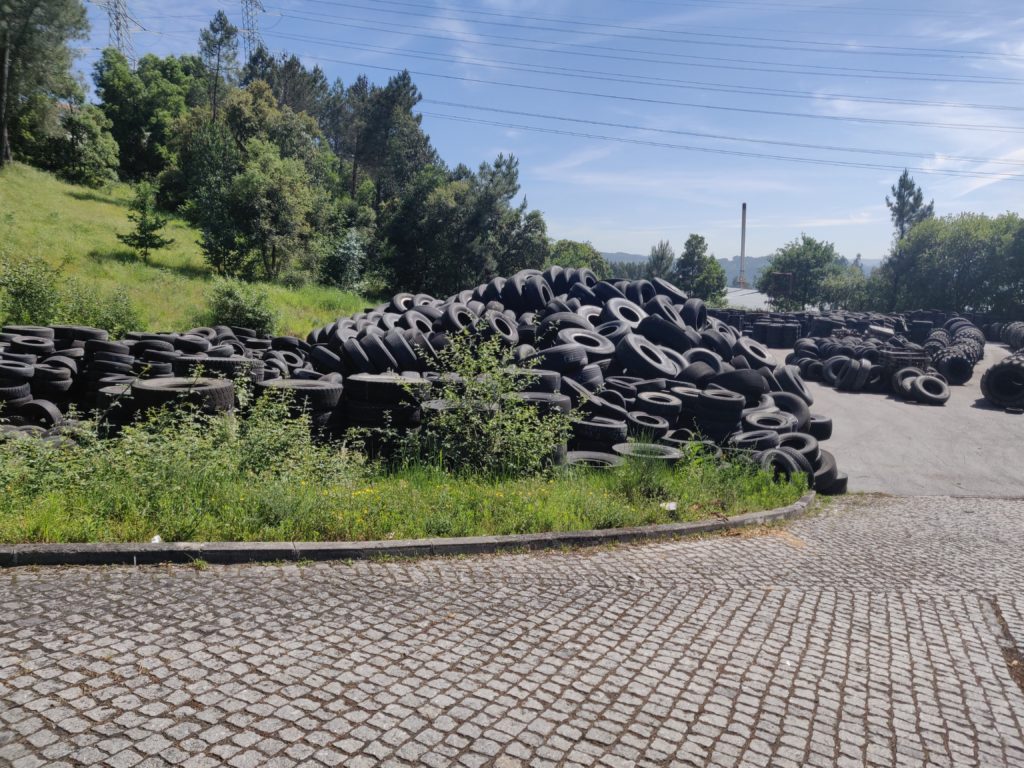
Pile of trashed tyres
Worn out tyre reused in a new contextScrap tyres have already been tested in various cases in the construction field, for example to make the roadbed of the streets and referred to as mechanical concrete, a method widely used in the USA. One of the most known cases is the Earthship Biotecture concept autonomous houses developed by architect Michael Reynolds, in which earth-rammed automobile tyres are used for building the main retaining wall of the house. This technique is presented as the most appropriate method for its strength, economy and low need of technical skills.
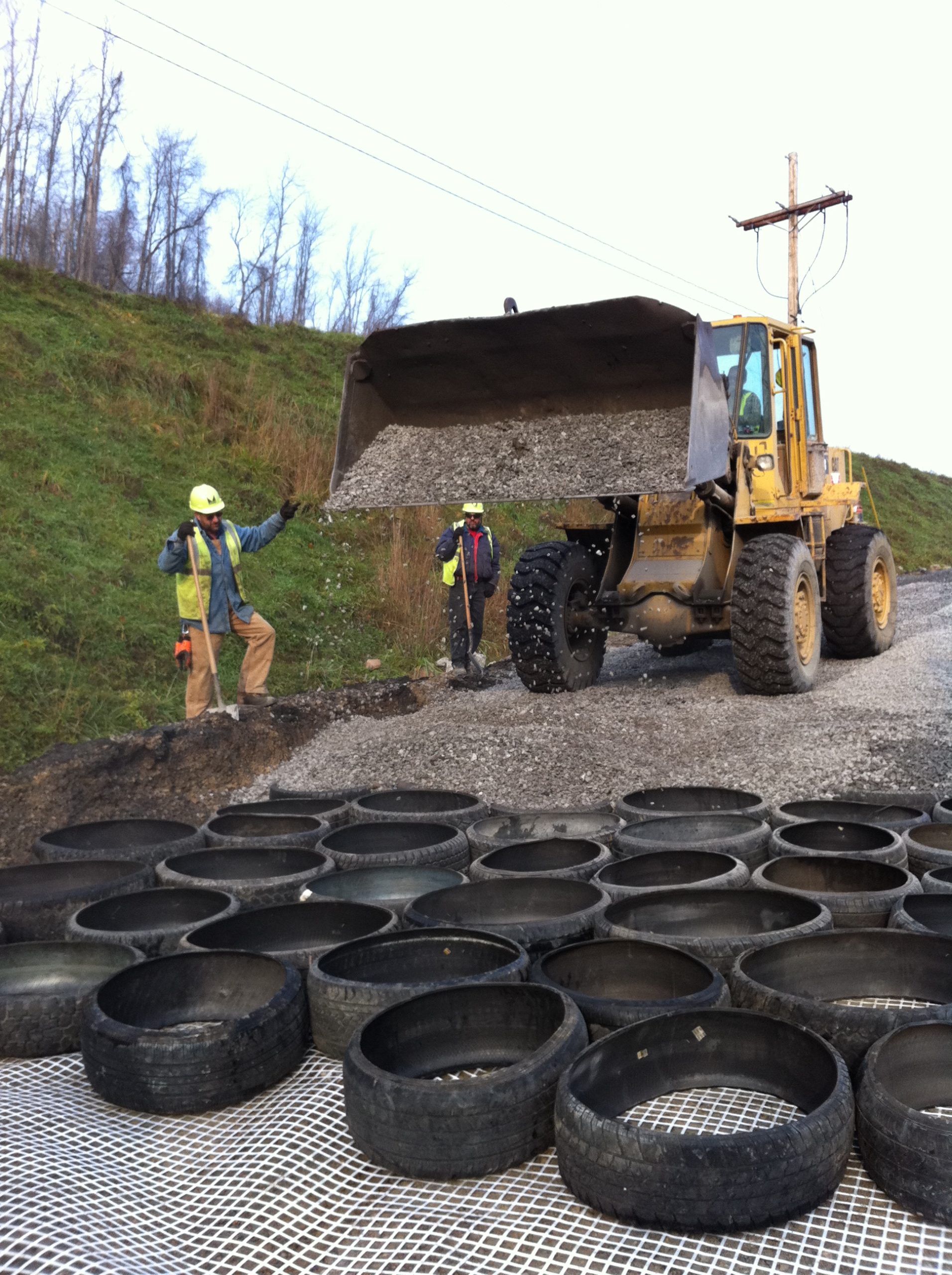
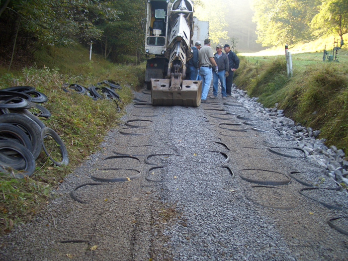
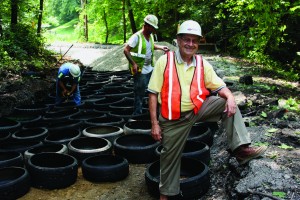
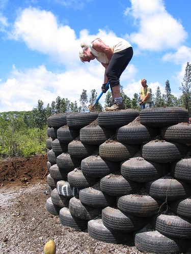
Pictures by mechanicalconcrete.com (pictures on the left) and by earthship_biotecture (licensed under CC BY-NC-ND 2.0) (picture on the right)
The flexibility of the tyre can also offer durable protection in a seismic area. These foundations can indeed reduce the effect of seismic vibrations on the building on top of them and it can be used in every stable soil, even clay soil (for more information click here). Yet we couldn’t find any applications that fits exactly our needs. Many cases used the tyres to build walls, or wall-like foundations where the structure was resting without anchoring. Other examples used conventional concrete to fix some kind of anchoring sockets. As far as we know, our case, a structure with several punctual load bearing columns, has not been well documented yet.
Interested in using this technology in your project?
Critical Studio can help!
Learn More!
Our Approach
In our particular case, we designed two single stepped footings for two columns of the green roof.
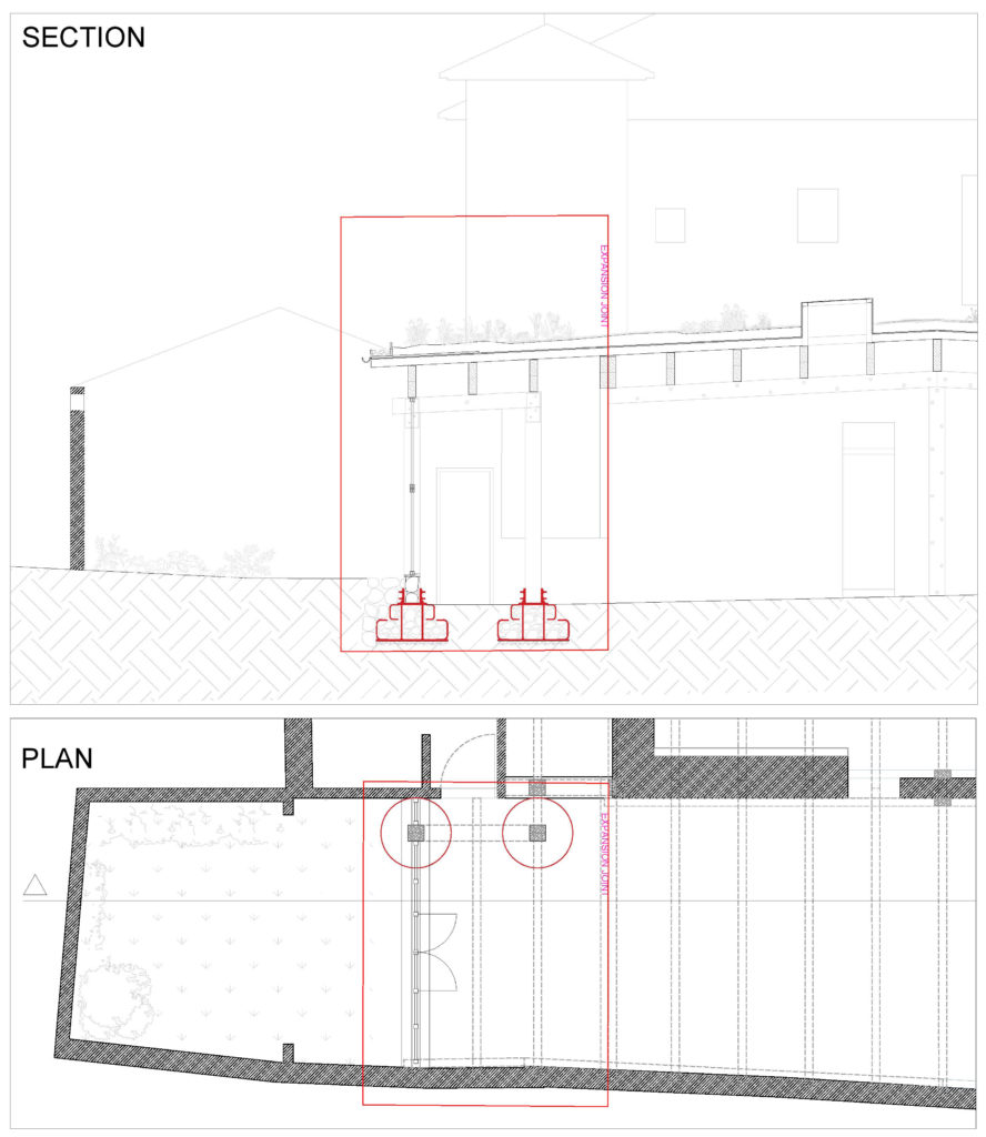
Section and plan of the two single stepped footings for two columns of the green roof
One part of the green roof structure lies on a massive, structurally stable granite wall built in the 19th century, and the other part will lay on the new foundation. Since it is a prototype and it is not well known how the foundations will react to the heavy load, we decided to make the new part (15m2) independent of the rest of the roof previously built (120m2). This assembly required us to insert an expansion joint which allows movement due to ground settlement or other variations, expansion or contraction of building materials. It will also assist the observation of potential changes and reduce the risk of damaging the whole roof in the worst case scenario. Indeed, this technique has been used in England for at least 15 years. Research and experiments of the Holy Trinity Church Tulse Hill showed that they tyre stacks will hold a minimum of 1000 kN/m2 of load with no detected movement on the expansion but a compressive variation of only 3mm (to watch the video click here). The IUT of Grenoble made tests of loading tyre foundations from the Flexagone office: They applied the weight of pressure of 72 tons on the foundation, without any damage or detectable movement (for more information click here).
Additionally we consulted several engineers to check our structural conceptions. As we explained in former articles, the heavy loads on the roof – composed of the drainage layer, earth and plants – impacts the renovation process by its load of 600 kg/m2– 5.88kN/m2, including the dynamic load. Based on this information and our needs, we developed the concept of single stepped footings for columns. We calculated that each pillar should carry about 2400kg approximately. The foundation includes a socket which joins it with the wooden column.
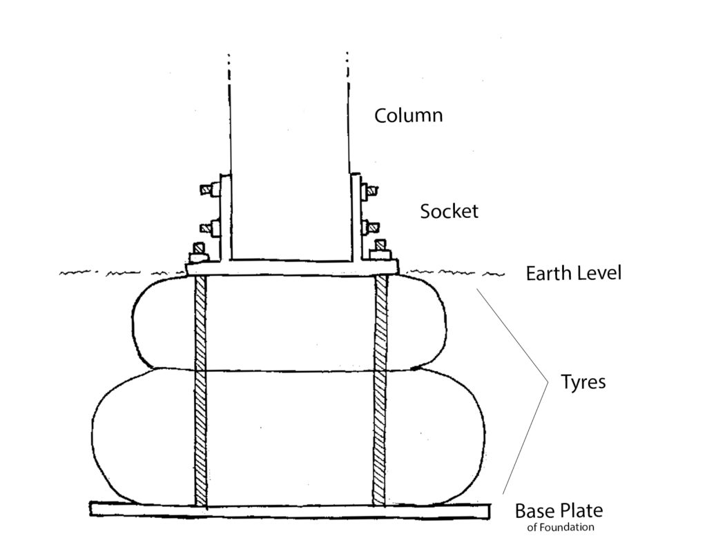
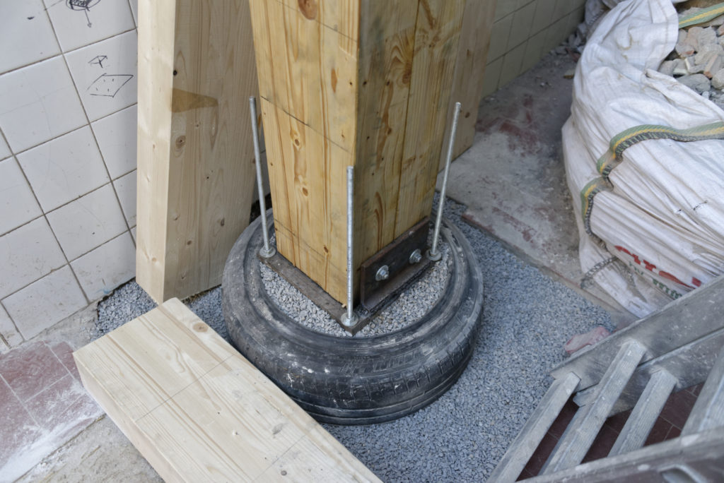
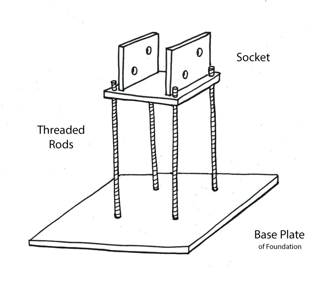
Section of the Tyre Foundation
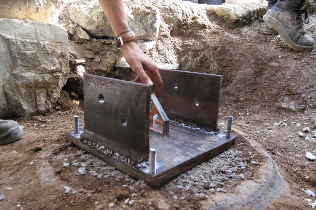
This connection is especially important while setting up the tyre and aligning the structure. Once the roof is finished, its own weight will hold its place. Below the foundation is a metal plate. On one hand, it distributes the forces on the soil and on the other hand it connects the foundation to the holding socket of the column. On top of the metal plate lay the tyres. We chose two tyres to make the foundation strong enough for the load. One truck tyre (95cm ø) and a smaller car tyre (65cm ø). The holding socket for the column is layed on the upper tyre and connected to the foundation through threaded rods which are welded to the base plate. The socket itself also holds the column in the right position.
Our workexplained step-by-step
This guide is an overview of every step we took in building our prototype of the tyre foundation. Since it was our first attempt, not all of our processes are optimized and need further development. However, this should serve as an inspiration for anyone with a similar situation and is open for discussion and improvement.
Beforehand a list of tools we used
in the progress:
welding machine,crowbar,grinder,hammer,wheelbarrow,bench drill,shovel,cutter.
Throughout each phase, we remind you that it’s important to protect yourself using appropriate safety equipment.
For this, you will need:
helmets,protective goggles,appropriate protective gloves,security shoes,reusable dust masks.
Preparation of the ground
The first and most important step before starting any foundation is the analysis of the ground. The soil has to have a sufficient bearing capacity. If the soil is not suitable there are different possibilities like reinforcing the soil, digging deeper, or adapting the foundation type to a wider tyre for example. In our case, we needed to dig until +/- 70 cm under the floor level to find a proper soil. We decided to put a layer of 5 cm of compressed gravel, frequently used under footings to have a correct level.
Estimated time: 6 to 8 hours per pit,
depending on the toughness of the ground
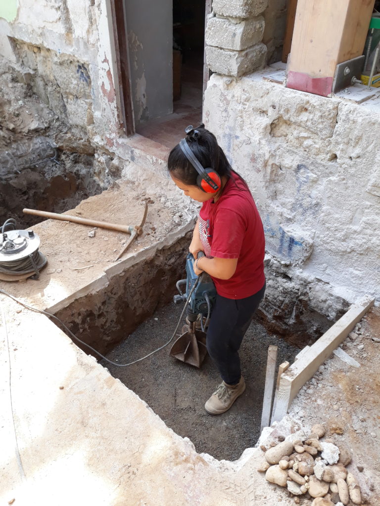
Leveling the ground of the pit
The base metal plate
The metal plate is the base of the foundation and serves as a solid surface for the tyres. We chose a thickness of 2 cm. To have the plate and also the column connected to the foundation we welded 4 threaded rods to the plate. The socket will be attached to these rods later on. Before putting the plate in the pit we put a breathable and waterproof membrane supposed to protect the plate from humidity in the ground. An EPDM membrane might have been a more suitable choice to increase the durability of the protection. We tried to wrap the plate as well as possible. Additionally, we painted the base plate and especially the weld joints with anti-corrosive paint. We still don’t know how this will react with the time, neither if it is going to be efficient enough to protect the welds. Our main objective is to take all the necessary precautions to avoid that water eventually permeates and settles at the bottom of the foundation. In our next tyre foundation build, we would consider drilling some holes in the metal plate to allow for the draining of water infiltration. The use of this metal plate was advised by our engineer to level the ground on which the foundation itself would set, but we didn’t find any other project using a similar precaution. It was also helpful for us to link the column to the foundation on a robust way.
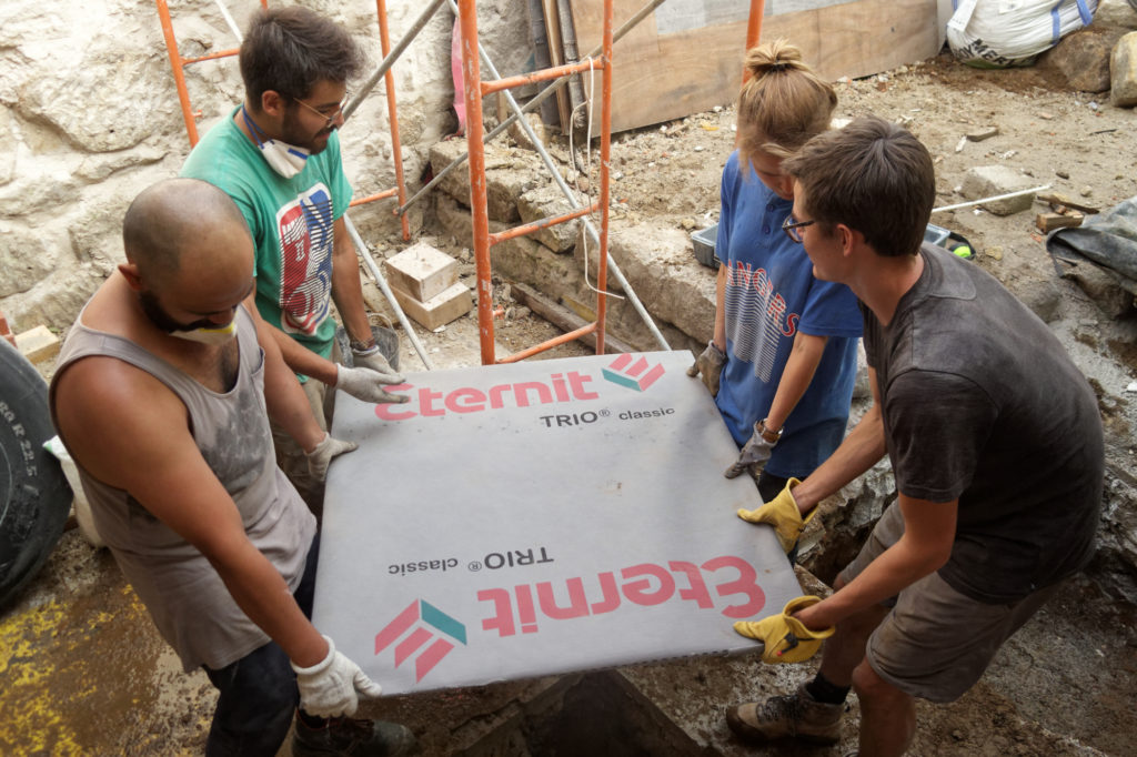
Metal plate wrapped with membrane
Estimated time: 2 to 6 hours,
depending on accessible tools to cut the plate on the good dimensions
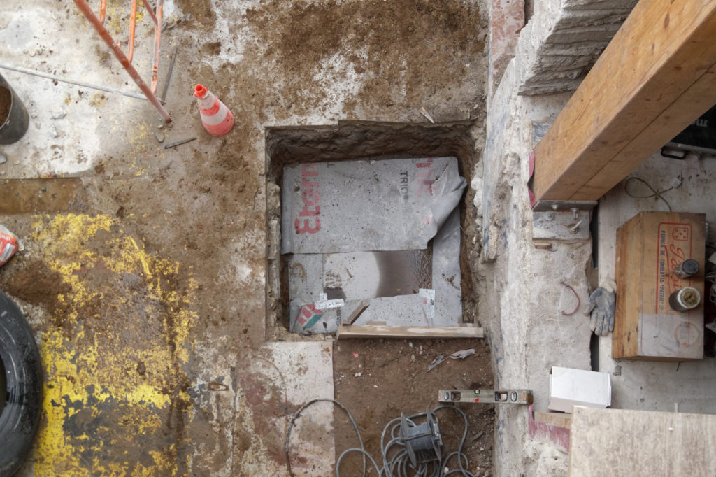
Metal plate on the ground of the pit
Preparation of the columns
The columns we used are made out of two 12×24 cm construction plywood beams. To join the two pieces we glued and screwed them together. The section is therefore 24×24 cm. To protect the wood from fire, water and pests we applied a layer of wood ash on the tyre, as well as protected the wooden column with a layer of borax, known as a protection against mold and repellent against insects. For a specific protection to prevent a specific termite attack, we paint the column with a mix of essential orange oil (5%) and linseed oil (95%). We will soon dedicate a detailed article to wood protection from fire, water and pests.
Estimated time: 2 hours.
Preparation of the socket
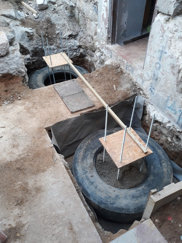
We used a steel socket to fix the column with the foundation. The socket is connected to the foundation with four threaded rods. It is fundamental to align properly the rods after putting the base plate, so that the columns would be aligned to each other. We used a wooden guide to secure the rods’ position while filling the tires. This guide is composed of two pieces that represent the two plates, with the holes for the threaded rods, and a long bar that helps to maintain them aligned and in place.
Metal plate on the ground of the pit
Estimated time: 4 to 6 hours,
depending on accessible tools to cut the steel and drill the holes.
Checking the alignment
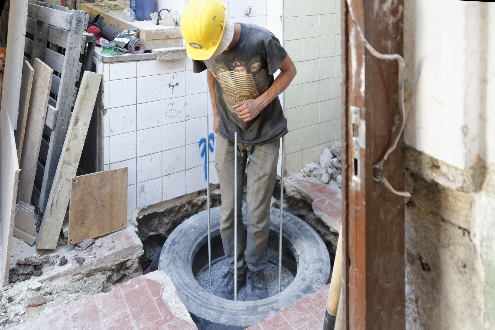
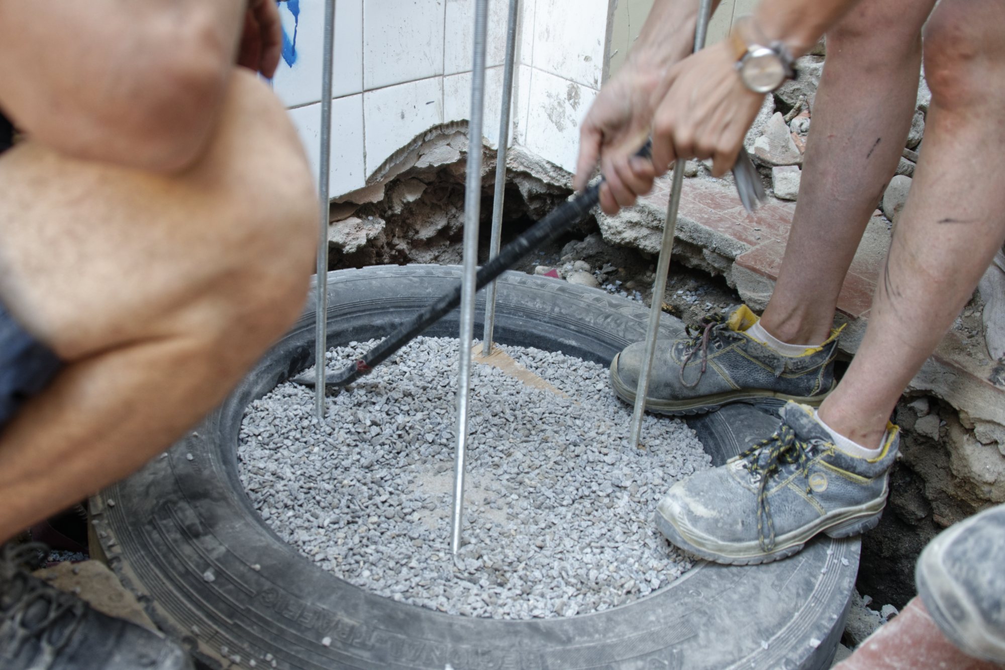
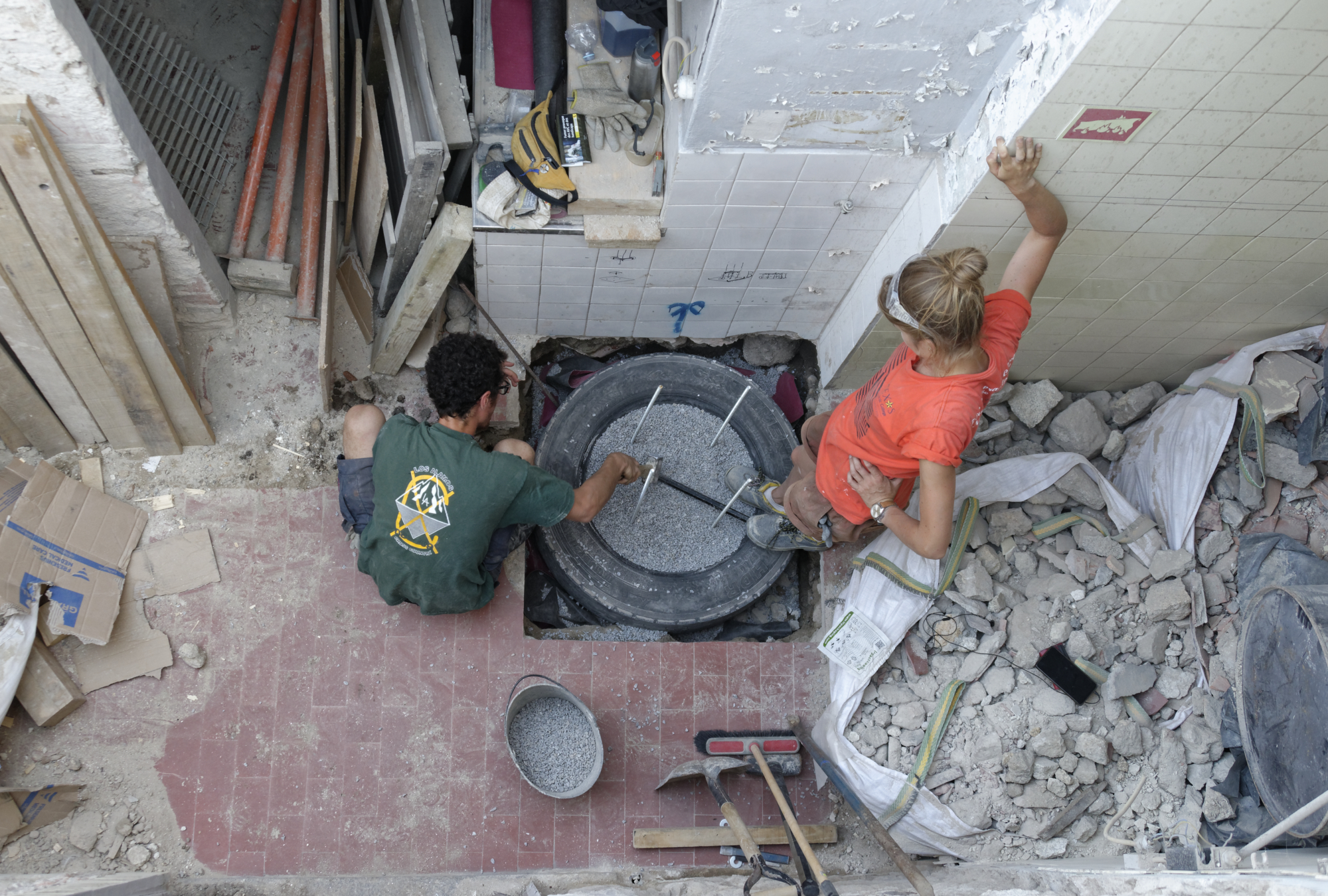
Filling of the tyres
In its rawest form, the tyres can only be filled with earth. Lots of case studies for earth filled tyre foundations are in relatively dry climates where the temperature doesn’t go below 0°C. It is preferable to use an other sub-grade as gravel or other material to encourage drainage and allow for water expansion, and then avoiding some major instability in the ground caused by frost. We decided to choose gravel made of local accessible granite, from the North of Portugal. We had the choice of three sizes of gravel. After some discussions with our engineer, we decided to order the smallest to have better cohesion. We also added some sand to create a mix with better bonding and leave no empty space between the gravel. We used the ratio of two parts gravel to one part of sand (2:1). The mix in the tyres has to be then as compressed as possible. At first, the tyre can be filled with a shovel and by hands. When it is not possible to get any more of the mix in, a crowbar and a piece of wood can be used to open the tyre (see how they did at the Holy Trinity Church Tulse Hill). Once held open, a second person can continue to fill up the space with the mix. A piece of wood can be used to shove the mix in as deep as possible and a hammer to compress it. This needs to be done until the tyre is inflated and no more mix can be added. The foundation is now ready for the socket.
Estimated time: 6 hours for two people to fill the 2 tyres for one foundation
(a truck and a car tyre).
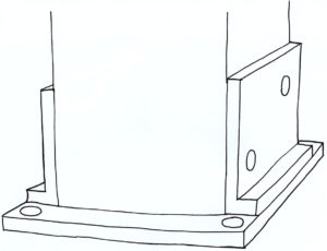
Installation of the socket
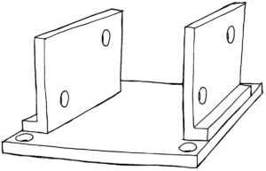
The steel socket which is holding the column is made out of three pieces of steel. The objective is to obtain a socket that correctly holds the column. We thought about different forms and finally settled with a “U”-form, that could maintain the feet of the columns and be correctly fixed to the lower part of the foundation.
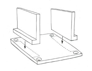
Base plate
The first part being the base plate (30x30cm), which has four holes to be fixed with the threaded rods of the foundation. The holes of the plate have to line up with the position of the threaded rods and should be 1mm bigger than the diameter of the rods to facilitate their insertion. Our rods were 12mm diameter. The second part being the two steel brackets (15x20cm), which are welded to the plate and hold the column with two horizontal threaded rods. The individual steps of this process are explained below.
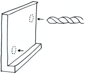
(1) The holes in both of the brackets, which should be shifted, can be drilled and should be at least 2-3mm bigger than the rods.
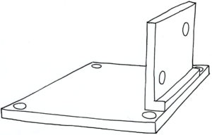
(2) Afterward, the first bracket can be welded on the base plate.
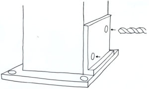
(3) The piece, that results from this step can be used to mark the position of the holes on the wood of the column. For this, half of the steel socket can just be laid on the column.
Image
(4) It might be necessary to cut a little edge of the column so there is some space for the weld. After marking the holes, they can be drilled also 2-3mm bigger than the rod. The bigger the holes are, the more room there is to adjust and compensate for potential inaccuracies.
(5) The next step is to find the right position for the second bracket. For this, the socket can be laid on the floor, and the column can be put on it. The rods can be stuck through the holes of the first bracket, the column and the second bracket, which is not fixed yet. Also, the bolts can be put on and tightened.
Column steel base plate sketch
(6) The second bracket should now touch the base plate and there should be no gap. If it doesn’t, any holes can be drilled bigger to make it fit properly. If it fits, it can be fixed by welding on 4-5 small points. Afterward, the column can be removed. The second bracket should be in the right position and can now be welded on completely.
Estimated time: 5 hoursto install the socket: drill, weld and adjust.
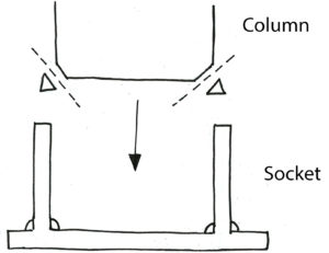
Installation of the columns
Once the socket is welded together in the “U”-form and the holes are drilled, the foundation is ready to receive the columns which have a section of 24×24 cm.Having an even level foundation is crucial and is something to pay extra attention to, during all the process. First, we used the spirit level to check the level of the lower plate, to ensure that the tyre will be placed on level ground. Indeed, it is important to keep in mind that the column will apply a heavy load that needs to be properly transferred to the foundation. For the next steps, the laying of the tyres and the fixation of the socket, make sure to always keep checking the level and the alignment of each foundation.
Checking the level of the metal plate
Estimated time: 2 hours.
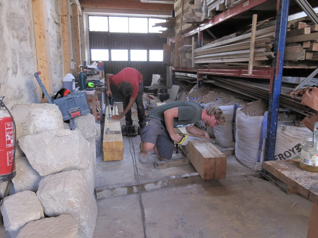
Preparing the columns
The retaining wall
In our case, one of the foundations is positioned under the level of the earth, in an outside environment, that forced us to find a solution for the rainwater not entering inside the workshop space. A retaining wall has been constructed to withstand lateral pressure of soil, due to earth and rainwater. There are a lot of different retaining walls, used for different situations for example the gabion retaining wall or the cantilever retaining wall.
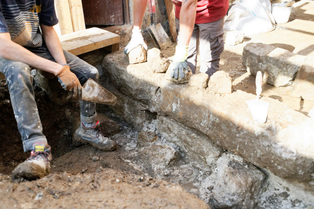
Building the retaining wall
In our case, we built a gravity retaining wall that depends on its self-weight only to resist lateral earth pressure. Commonly, this needs to be of large proportions because it requires a significant gravity load. We constructed the wall from granite stones that we had acquired from previous deconstruction of old walls. To protect the column from water infiltration, we bonded the stones with a lime mortar mix.
Furthermore, we plan to realize a drain which prevents rainwater from entering the basement. Parallel to the retaining wall, it will collect excess water and runs it through a pipe into a sump away.
Cost and Time Comparison
Since we are using the tyre foundation instead of a concrete foundation, the comparison of cost is a crucial point. For this reason we compare only the part of the foundation which is replaceable. The socket and the column are therefore not part of the comparison, since they are the same for both versions. We already pointed out the factor of sustainability, which is our driver in this matter. But what does this mean from an economical point of view? A tyre foundation in its simplest form is only made from dirt and scrap tyres and is therefore basically free. This method is suited for retaining walls and foundations that don’t require anchoring. Our Approach of a highly stressed single step footing which includes anchoring cost approximately 125€ compared to the concrete version of approximately 28€. As the calculation shows, the major cost factor is the metal plate which is also an open question for us. Its necessity is not completely clarified wherefore we are looking for alternatives which even out differences in price and make the single step foundation an economically competitive alternative.
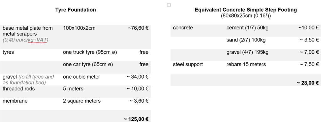
It is to be added that the concrete should be mixed homogeneously by a cement mixer rather than by hand, and that welding the steel reinforcement takes some time as well and electricity, and quite a few welding electrodes. In terms of time, the concrete takes at least 7 days to set sufficiently for a foundation in order to set-up the column, but is faster to make, comparatively.
Conclusion
In the process of finishing the green roof, the application of the tyre foundation has been challenging but successful so far. It is carrying the roof structure but needs further observation as to how it will react under the full load of the green roof including soil and vegetation. To be able to observe any kind of movement we installed a measuring unit that we will control regularly.
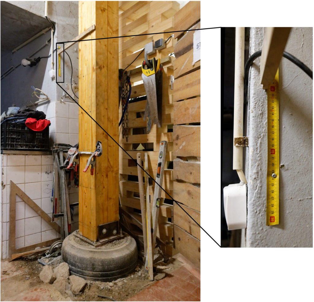
Movement measurement
Sustainable Satisfaction?
Concrete is an extremely popular material for construction and can be found in most parts of the world. Today concrete is the primary material used for foundations because of its many positive attributes: it is strong in compression, it is flexible as it can be poured into adapted forms and sizes, it can be applied in situ, it has good fire resistant qualities. However, the production of Portland cement, an essential constituent of concrete, leads to the release of significant amounts of CO2 and other greenhouse gases. Because of limited natural resources, such as sand, and the output of greenhouse gases, concrete production is not sustainable and therefore requires alternatives in the construction field. A possibility is to use recycled materials which have low energy costs, high durability and low maintenance requirements and therefore a small impact on the environment.
The single step footing foundation represent a viable and affordable alternative method we are looking forward to developing and using in further projects.
You want to see more? Check out the video to see how we experimented with scrap tyres and compressed earth&gravel for a low-impact and concrete free building!
Sources
[Ar. Bindu agarwal, Ar. Aanchal Sharma] “Reuse of Waste Materials: A case study of Earthships”, in: International Journal of Science, Engineering and Technology Research (IJSETR) Volume 6, Issue 10, October 2017, [Online] available at: http://ijsetr.org/wp-content/uploads/2017/10/IJSETR-VOL-6-ISSUE-10-1364-1369.pdf (Last accessed in December 2019).
[Architecture 2030] “Buildings generate nearly 40% of annual global GHG emissions”, [Online] available at architecture2030.org/buildings_problem_why/ (Last accessed in December 2019).
[Andrew, Robbie M.] “Global CO2 emissions from cement production, 1928–2018”, CICERO Center for International Climate Research, [Online] available at: https://www.earth-syst-sci-data-discuss.net/essd-2019-152/essd-2019-152.pdf (Last accessed December 2019).
[Decorex Pro] “Technology for the construction of the foundation of tires”, [Online] available at: /en.decorexpro.com/fundament/iz-pokryshek/ (Last accessed in December 2019).
[Department for Business, Innovation and Skills London] “Estimating the Amount of CO2 Emissions that the construction industry can influence”, [Online] available at: https://assets.publishing.service.gov.uk/government/uploads/system/uploads/attachment_data/file/31737/10-1316-estimating-co2-emissions-supporting-low-carbon-igt-report.pdf (Last accessed in December 2019).
[Deva Racusin, Jacob; McArleton, Ace] “The Natural Building Companion: A Comprehensive Guide to Integrative Design and Construction”, 2012
[Flexagon Office] “Fondations et plots”, in: La Maison Ecologique 67 – fevrier et mars 2012, [Online] available at: http://yourtes.net/fichiers/Fondations%20et%20plots%20-%20La%20Maison%20Ecologique%2067%20-%20fevrier%20et
%20mars%202012.pdf (Last accessed in December 2019)
[Holy Trinity Tulse Hill on YouTube] “Packing Car Tyre Foundations (Car Tyre Foundations #4)”, [Online] available at: https://www.youtube.com/watch?v=0YV2TG5aypw (Last accessed in December 2019)
[Holy Trinity Tulse Hill on YouTube] “Car Tyre Foundations Plate Test”, [Online] available at: https://www.youtube.com/watch?v=K8Vlz6qNCfU (Last accessed in December 2019)
[König, H., Weissenfeld, P.] “Entretien écologique du bois”, ed. La plage, 2008.
[Lowimpact] “Why cement should never be used with natural buildings”, [Online] available at: https://www.lowimpact.org/why-cement-should-never-be-used-on-straw-bale-houses/ (Last accessed in December 2019).
[Mechanical Concrete] “Award Winning, Economical, Green, Industrial Strength, Construction Technology”, [Online] available at: http://www.mechanicalconcrete.com/ (Last accessed in December 2019]
[Miteco] “Descarbonatac fabrical”, [Online] available at: https://www.miteco.gob.es/es/calidad-y-evaluacion-ambiental/temas/sistema-espanol-de-inventario-sei-/040614-descarbonatac-fabric-cal_tcm30-429852.pdf [Last accessed in December 2019)
[Miteco] “Combust fabricamento”, [Online] available at: https://www.miteco.gob.es/es/calidad-y-evaluacion-ambiental/temas/sistema-espanol-de-inventario-sei-/030311-combust-fabric-cemento_tcm30-430164.pdf (Last accessed in December 2019)
[Naik, Tarun R.] “Sustainability of Concrete Construction”, [Online] available at: https://ascelibrary.org/doi/abs/10.1061/%28ASCE%291084-0680%282008%2913%3A2%2898%29 (Last accessed in December 2019).
[Russian Patents] “Module-type anti-seismic protective unit for buildings and structures”, [Online] available at: https://russianpatents.com/patent/225/2250308.html (Last accessed in December 2019]
[World Green Building Council] “New report: the building and construction sector can reach net zero carbon emissions by 2050”, [Online] available at: ww.worldgbc.org/news-media/WorldGBC-embodied-carbon-report-published (Last accessed in December 2019).
The post Tyre Foundations first appeared on Critical Concrete.